Casting Photos and Descriptions
The iron used for LocoGear’s castings is ductile iron. This is the same formula that is used for casting the beds of lathes and milling machines.
This is not just “Gray Iron” which is the bottom of the ladder in iron castings.
317-A-5009
Cylinder & Piston Valve3 Required
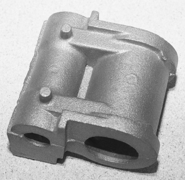
The prototype of the Cylinder and Piston Valve was a 17” dia. x 18” stroke cylinder and a 9” piston valve. This part was cast with a 1 3/4” piston core and a 7/8” valve core. The casting has the internal steam channels cast into it between the cylinder and valve cores.
The prototype of the Cylinder and Piston Valve was a 17” dia. x 18” stroke cylinder and a 9” piston valve. This part was cast with a 1 3/4” piston core and a 7/8” valve core. The casting has the internal steam channels cast into it between the cylinder and valve cores.
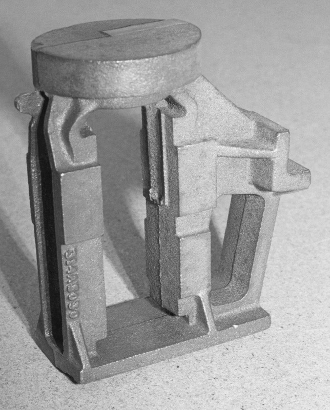
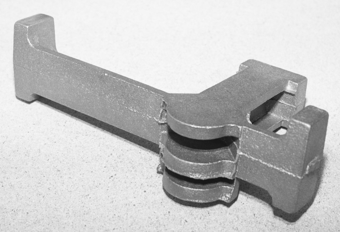
314-A-5030Cylinder Frame3 Required
The three Cylinder Frames rest directly on top of the Bottom Bracket. They hold guide the cross heads and support the Cylinders and Valves. The top of the cylinder frame becomes the bottom cylinder head where the piston rod exits the cylinder.
The three Cylinder Frames rest directly on top of the Bottom Bracket. They hold guide the cross heads and support the Cylinders and Valves. The top of the cylinder frame becomes the bottom cylinder head where the piston rod exits the cylinder.
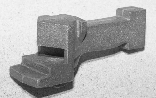
942-A-5103
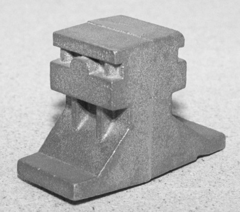
Valve Stem Cross Head Guide Bracket3 Required
The Valve Stem Cross Head Guide Bracket is a small bracket that holds the rocker in the valve link motion and hangs on the side of the Cylinder Frame. This part and others in this assembly can be found on the Link Motion plan 583-A-5008.
The Valve Stem Cross Head Guide Bracket is a small bracket that holds the rocker in the valve link motion and hangs on the side of the Cylinder Frame. This part and others in this assembly can be found on the Link Motion plan 583-A-5008.
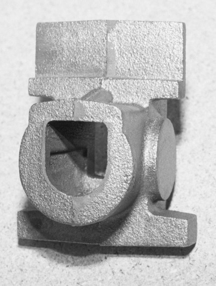
933-C-5069
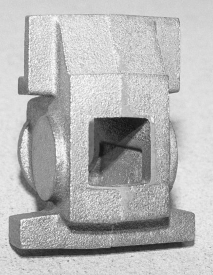
Journal Box (Front View)6 Required
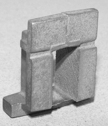
The Journal Box is on the gear side and also holds the line shaft with its pinion. Lima used brass friction bearings on their Shays. The photo on the left shows the front of the journal box. The round disks on either side show the position of the line shaft. The photo on the right shows the back of the journal box where the axle enters the journal box and the surface that comes in contact with the wheel.
The Journal Box is on the gear side and also holds the line shaft with its pinion. Lima used brass friction bearings on their Shays. The photo on the left shows the front of the journal box. The round disks on either side show the position of the line shaft. The photo on the right shows the back of the journal box where the axle enters the journal box and the surface that comes in contact with the wheel.
933-C-5069 Journal Box (Back View)6 Required
933-B-5064
Truck Pedestal 6 Required
The Truck Pedestal is a frame in which the left side journal box rides up and down. The journal box is fabricated (see drawing 932-A-5678).
The Truck Pedestal is a frame in which the left side journal box rides up and down. The journal box is fabricated (see drawing 932-A-5678).
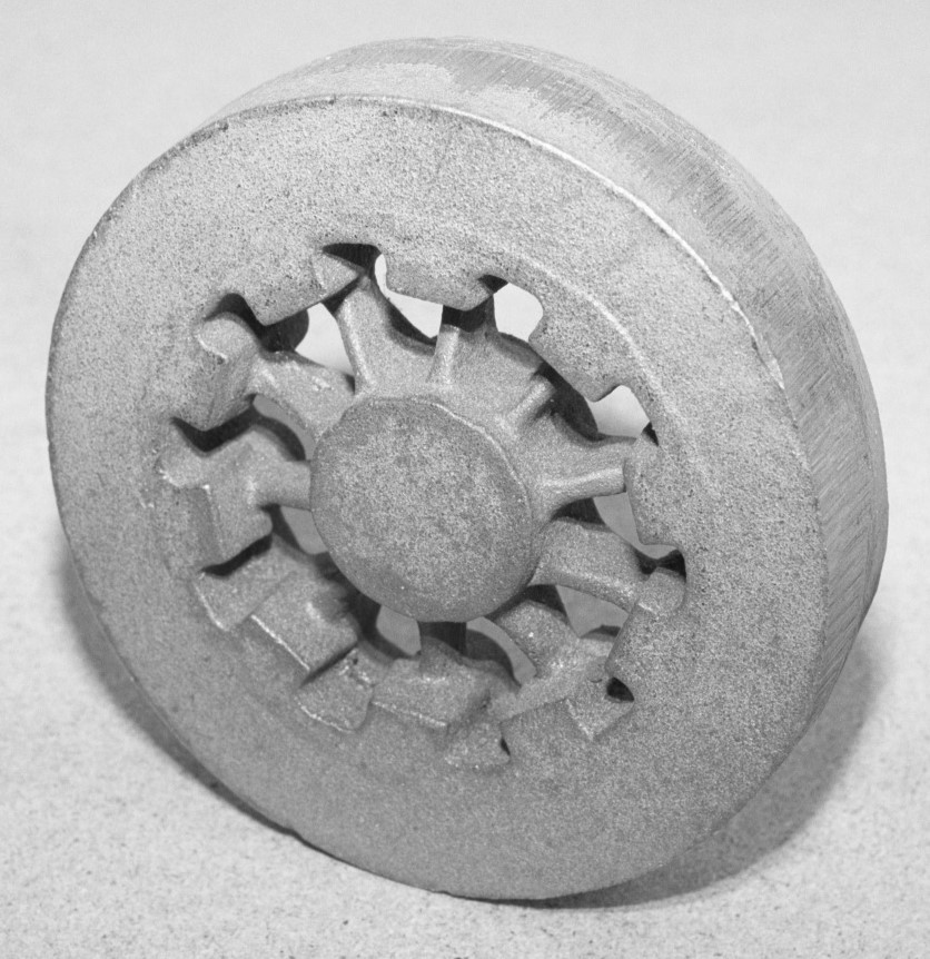
953-A-5014 Wheel Center (Outside View)12 Required
The Wheel Center casting is large enough to include material for the wheel tire and flange so the entire wheel can be one piece. However, a steel tire could be made as Lima did and pressed onto the wheel center machined down to the specifications on the original plan. The front or outside of the wheel is shown on the left with the square spoke bottoms and the back or inside of the wheel is shown on the right with the round spoke bottoms.
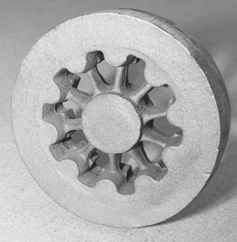
953-A-5014
Wheel Center (Inside View)12 Required
482-A-5085
Frame Boiler Saddle2 Required
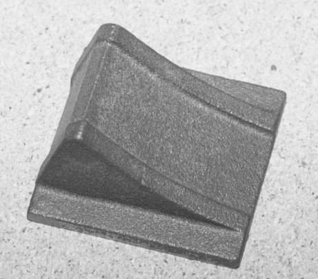
The Boiler Saddles are two curved brackets that rest on top of the front engine frame bolster and cradle the boiler to the frame.
The Boiler Saddles are two curved brackets that rest on top of the front engine frame bolster and cradle the boiler to the frame.
187-A-5017
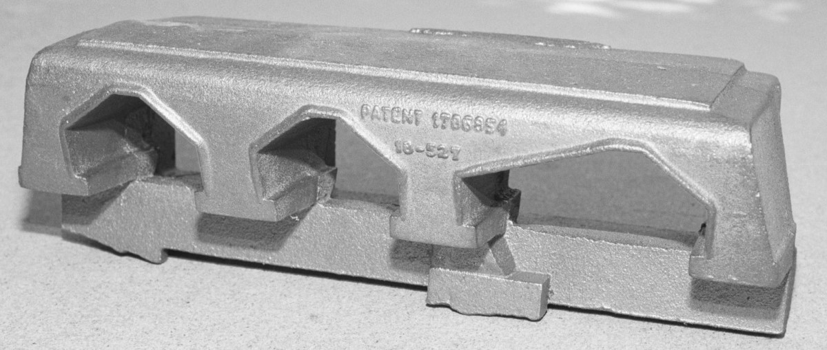
Bottom Bracket1 Required
The Bottom Bracket is the frame upon which the steam engine is built and holds the crankshaft. It is what gives the Shay its distinctive style with the three openings on its side for the crank shaft counterweights to rotate.
933-C-5066
Right Truck Frame3 Required
The Right Truck Frame is on the gear side.
The Right Truck Frame is on the gear side.
933-C-5067
Left Truck Frame3 Required
Left Truck Frame is on the non-gear side.
Left Truck Frame is on the non-gear side.
483-A-5071
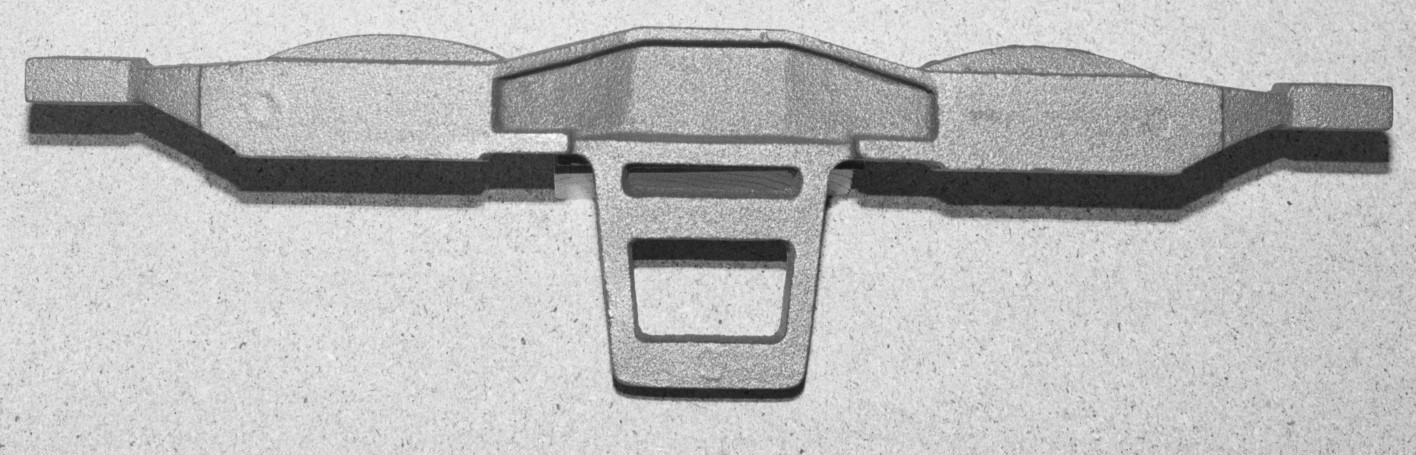
Frame End Casting 1 Required
The Frame End Casting is located at the tender end of the locomotive frame and is where the tongue of the tender draw bar is attached to the locomotive.
The Frame End Casting is located at the tender end of the locomotive frame and is where the tongue of the tender draw bar is attached to the locomotive.
373-A-5026
Draw Head2 Required
The Draw Head is the coupler head pocket.
The Draw Head is the coupler head pocket.

932-A-5229
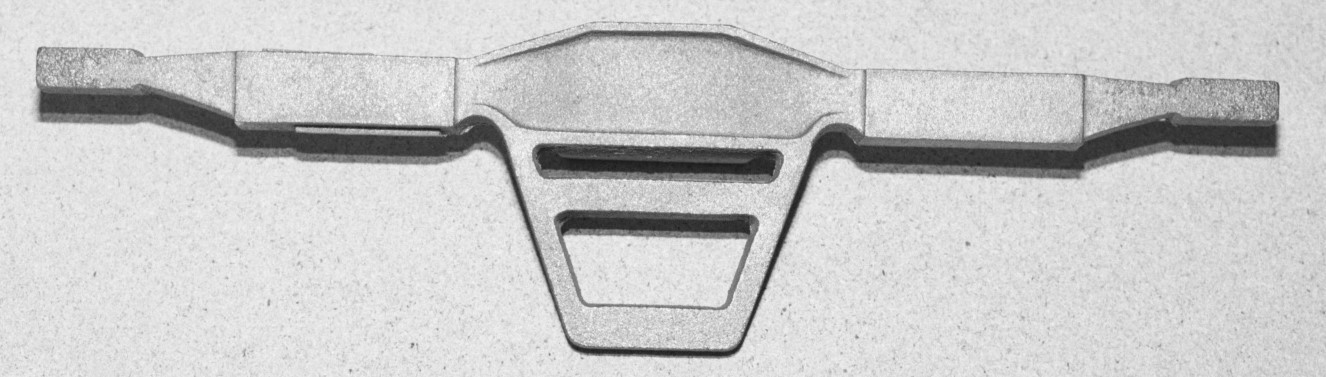
Truck Frame Yoke 2 Required
The Truck Frame Yoke is a bracket on the front of the front truck and the rear of the rear truck. It connects the ends of the truck frames and allows the truck to swing around and under the coupler (draft gear) pocket.
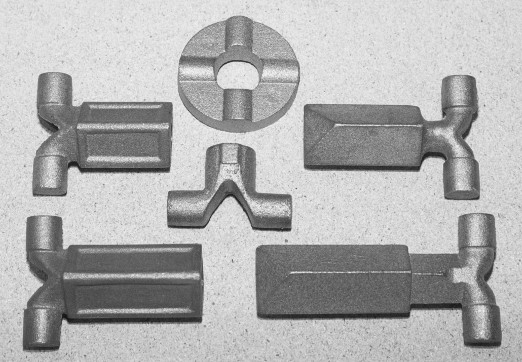
742-A-5464 7″ Square Shaft Short (upper right)1 Required
742-B-5466 7″ Square Shaft Long (lower right)2 Required
743-B-5143 Slip Coupling Long (lower left)2 Required
743-B-5143 Slip Coupling Short (upper left)1 Required The 7″ Square Shafts and Slip Couplings allow the line shafts to slide when the trucks swivel while maintaining power transmission to the trucks.
742-C-5461 Line & Crank Shaft Coupling (center)6 Required The Line & Crank Shaft Coupling is a small yoke which is attached to each end of the crank shaft and to the ends of the line shafts.
743-A-5142 Coupling Ring (upper center)12 Required The Coupling Ring is universal joint. Lima designed this as a two piece ring, but because that design can not be machined in this scale, the coupling ring has been redesigned into a three piece ring. A central ring can be machined from steel bar stock and then two Coupling Ring castings are bolted to the central ring. A scale drawing (743-A-5142) is available to explain this new design.